Stampy Prototypes - RP2040 USB-C Controller Board for Handwiring

$10.99

Heavily inspired by the Postage Board Mini by LifeIsOnTheWire, Stampy is an RP2040-based version of it for doing a handwired build.

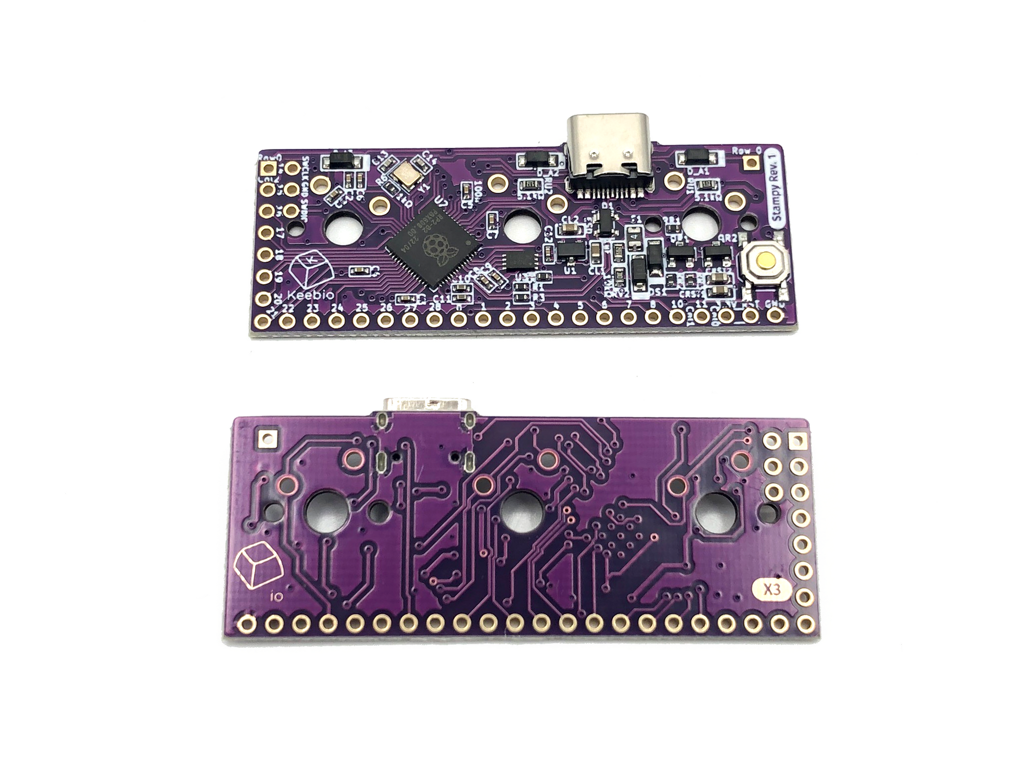
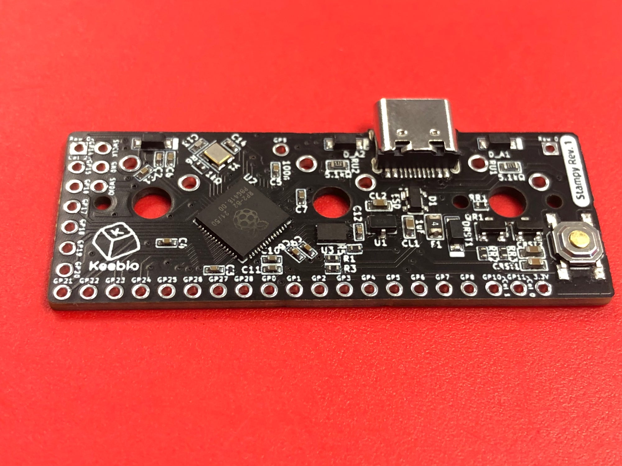
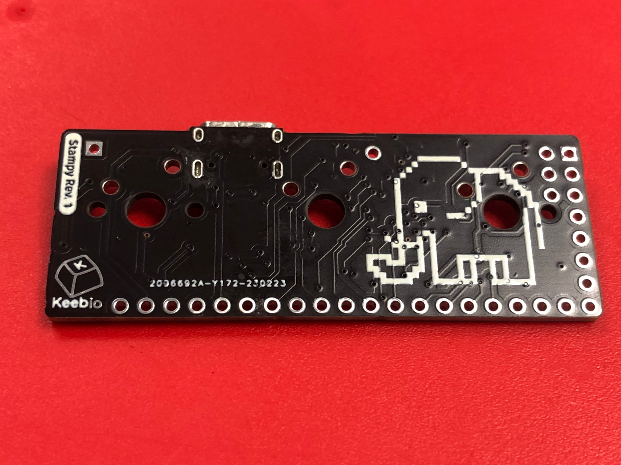
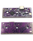
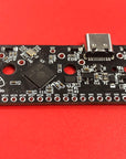
There are two sets of prototypes of the Stampy board. The differences between these prototypes vs. the final production version are the following:

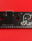
  • Prototype 1 (Black)
    • 16Mbit (2MB) of flash memory
    • Lacks VBUS detection circuit (this really only matters a bit for split keyboard builds)
    • Has access to GPIO9 (production version loses this pin due to it being used for VBUS detection)
    • Lacks breakout pin for RESET
  • Prototype 2 (Purple)
    • 8Mbit (1MB) of flash memory
    • Has VBUS detection circuit on GPIO9
    • Lacks silkscreen on top side of board (missing text on Keebio logo and missing elephant)
    • 3.3V breakout pin is actually not connected to anything
    • Marked with X3 on top side of PCB

    What is Stampy?

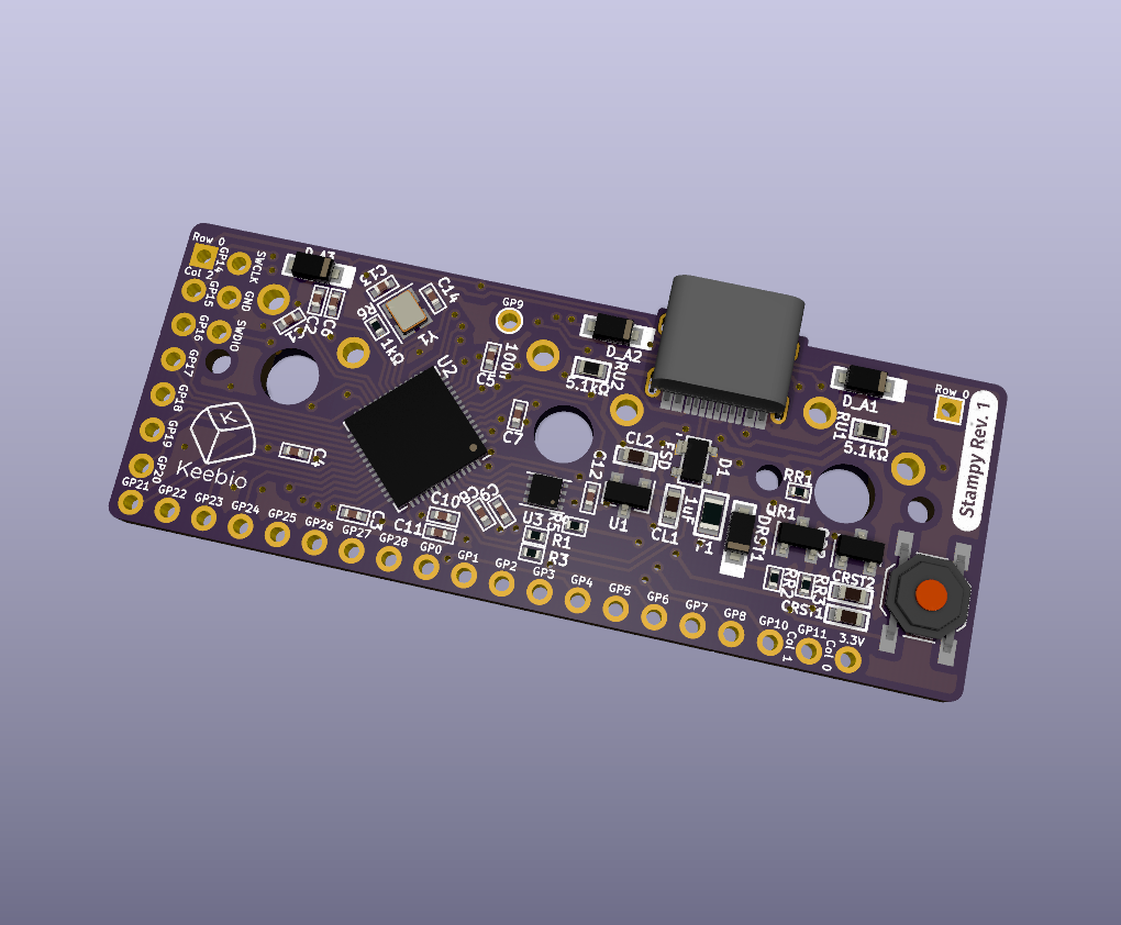
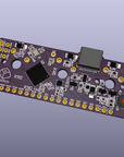
    Stampy is a controller board meant to assist with the construction of a hand-wired keyboard. Instead of using some other daughterboard like the Pro Micro, Elite-C, etc., Stampy gets soldered directly to 3 switches, meaning that no extra space below the controller is needed.

    Goes great with the Amoeba Single-switch PCBs!

    Features

    • RP2040 Microcontroller
    • Compatible with both Cherry MX style switches.
    • 26 I/O pins available for your rows and columns, or other IO functions such as LEDs and RGB strips
      • 3 pins are preset for columns, and 1 pin is preset for a row
    • Can cover well over 100 switches
    • USB Type-C connector
    • QMK-compatible

    Usage Notes

    For full information about the Stampy, see the Stampy Usage Guide.

    Pin Assignments

    4 of the pins are connected to the 3 switch locations in the following way:

    • Row 0 - GPIO14 (All 3 switches are connected to Row 0)
    • Col 0 - GPIO11 (Left switch)
    • Col 1 - GPIO10 (Center switch)
    • Col 2 - GPIO15 (Right switch)

    The reset button is connected to RST and 3.3V (not GND).

    Switches

    Due to the tight spacing of components, if you are using 5-pin switches, you will need to clip both of the plastic pins for the Center switch and the left plastic pin for the Right switch.