Tragicforce 68 - MF68 TMK/QMK - Magicforce 68 PCB Replacement Kit (Discontinued)

$8.99

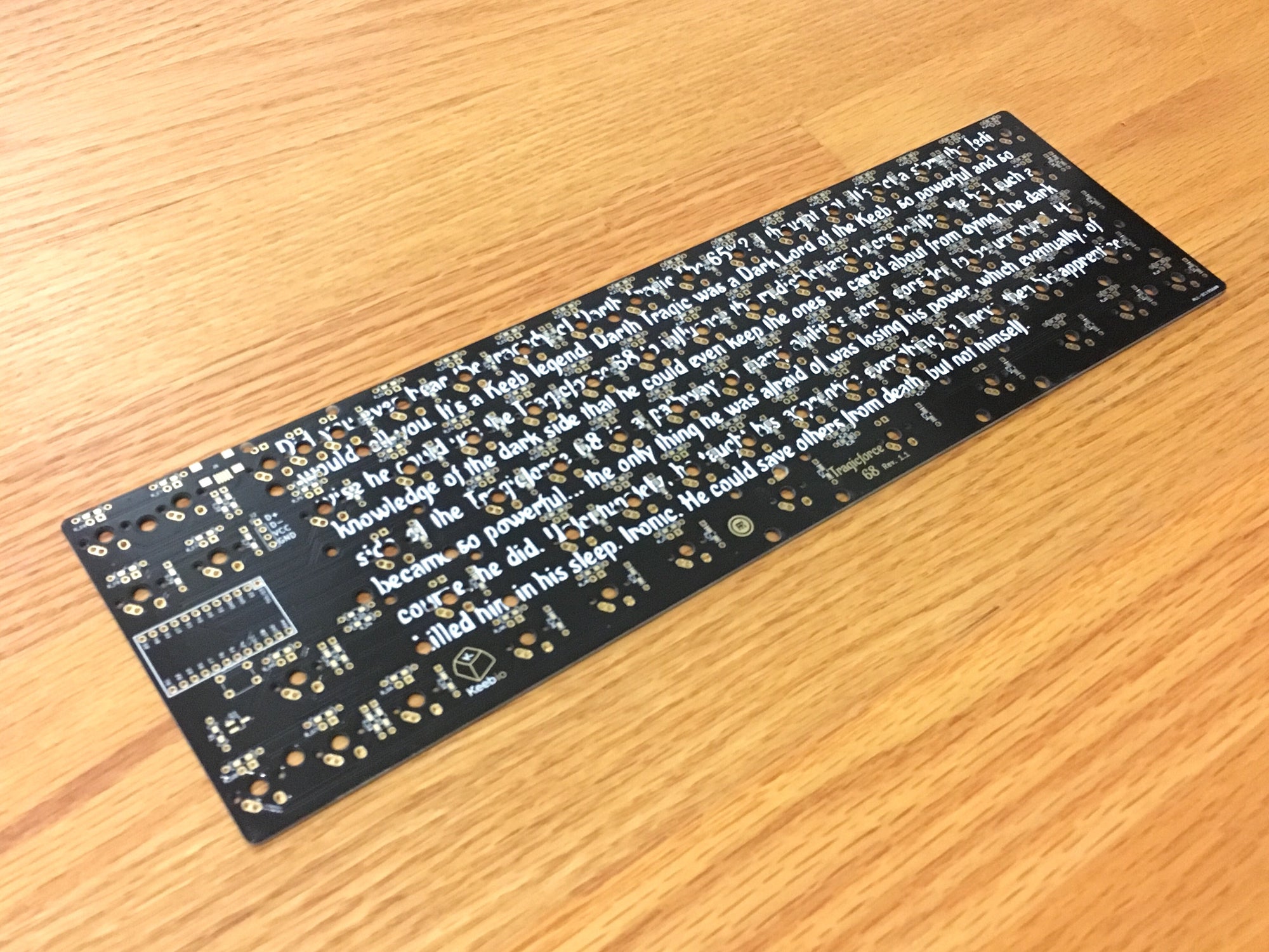
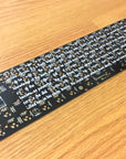
Looking for the ability to reprogram your Magicforce 68 keyboard or have backlighting? Here's a replacement board for it that lets you use custom firmware like TMK or QMK so you can set your own keymap.

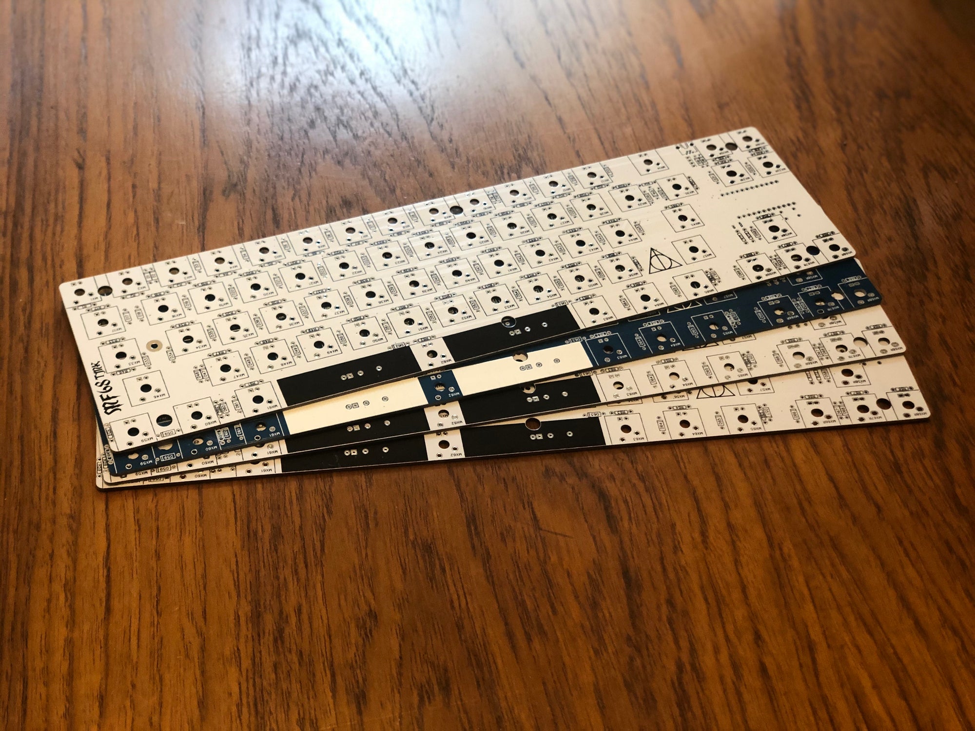
MF68 PCBs: Found a few extra MF68 PCBs from previous sale. Only includes the PCB, no reset switch/MOSFET/pigtail/etc.

Rev. 1.0 Scrap Sale!: On the Rev. 1.0 board, the PCB-mount stabilizer orientation does not match up with the Magicforce 68 case. The board works fine fine with Plate mount stabilizers. The scrap sale only includes the PCB, no reset switch/MOSFET/pigtail/etc.

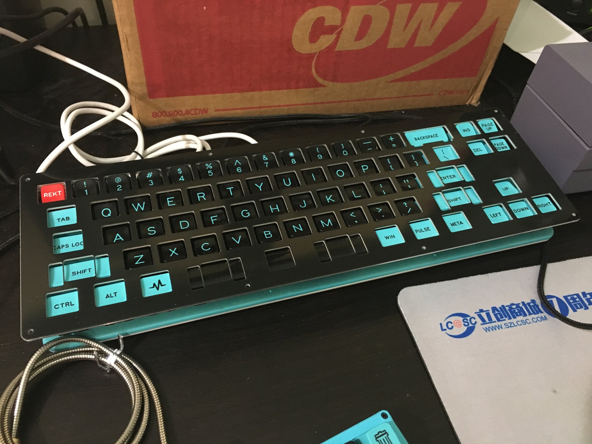
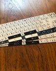
New! Plate kits designed for stand-alone usage (i.e. no Magicforce 68 case needed):

  • Plate Kit: Top plate, bottom plate, standoffs, and screws. Top plate compatible with Rev. 1.1 PCB only using PCB-mount stabilizers, does not support Plate-mount stabilizers
  • Plate Kit + Rev. 1.1 PCB Base Kit: Same as Plate Kit above plus:
    • Rev. 1.1 PCB
    • Mini-USB port
    • 4.7kΩ resistor for MOSFET
    • 1 AO3416 MOSFET
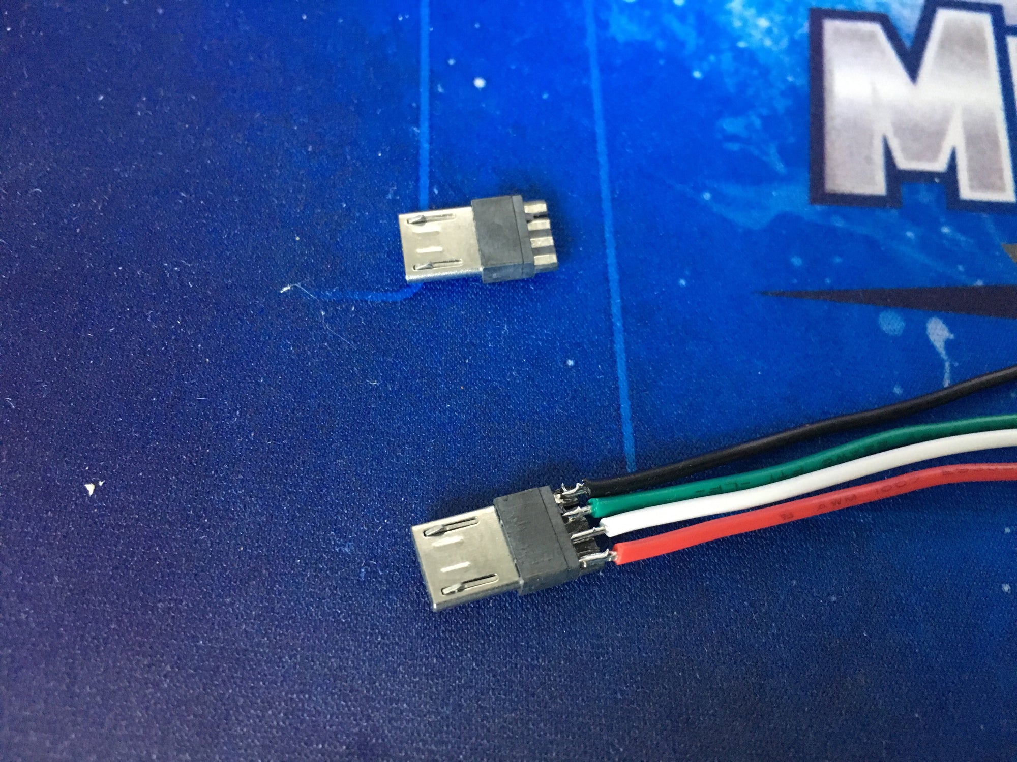
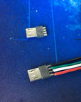
    • Micro USB connector to create pigtail (wires not included)
    • Reset switch

The Tragicforce 68 PCB is a redesign of the MF68 PCB, and sports the following features:

  • MX/Alps switch support
  • In-switch LED support
  • Ability to use PCB-mount stabilizers instead of the stock plate-mount stabilizers
  • Split space support (requires modification to plate)

Kit Includes:

  • Tragicforce 68 PCB
  • 4.7kΩ resistor for MOSFET
  • 1 AO3416 MOSFET
  • Micro USB connector to create pigtail (wires not included)
  • Reset switch

Does not include:

Build summary:

  1. Solder diodes, resistors, MOSFET, push button, and Pro Micro
    1. For the Pro Micro, it is recommended to remove the plastic on the header pins after soldering them on so that the Pro Micro is flush with the PCB
  2. Desolder old Magicforce 68 PCB
  3. Add new switches to plate (if replacing them) and solder them to the new PCB
  4. Create pigtail using the Micro USB connector
  5. Drill hole for reset switch
  6. Reassemble case